Published
by Olivier Mathieu, Market Development Manager
Advanced Electronics Solutions
Electronic systems rely on efficient combination and distribution of voltages and currents from different sources. In high-power applications, such as industrial drives, renewable energy inverters, powertrains for electric vehicles and converters used in rail, energy must be channeled with minimal power losses. For engineers of these inverter systems there is an ongoing challenge to develop power distribution components, such as laminated busbars, that are rugged enough to handle high power levels, minimize the overall DC link inductance, and increase the performance and operating lifetime of inverter systems.
Simulation technologies can help optimize the design by depicting an overall reasonable, secure and fast analytical tool for the entire inverter or individual components of the system. Using a simulation not only helps designers and engineers determine certain flaws and limitations in their product and model, it also helps them build fewer prototypes. Thus making the overall design process much cheaper.
The increased focus on electrification in the transportation sector increases demand for smaller, lighter, cheaper and more efficient inverters used in drivetrains. In most of these inverters, the DC link system that includes busbars and capacitors make up a large portion of the total inverter. For this reason it is beneficial to use a simulation to evaluate how well the design meets the initial requirements regarding the inductance and thermal management.
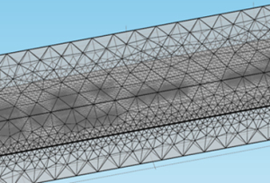
The simulation at the busbar level can typically be broken down into three different types of simulations:
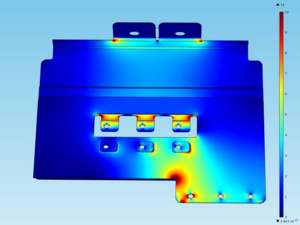
The inductance simulation is the most complex simulation, but virtually any design can be evaluated independently of busbar main body, terminals, or capacitor connection. It is essential to lower the inductance in the DC link system of any modern inverter. It minimizes the switching losses in the inverter and avoids voltage peaks during commutations.
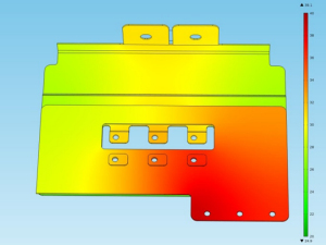
The power density and heat of a busbar help determine how compact it can be made for a given power rating. However, the general trend in electronics is moving towards smaller devices handling higher levels of power density.
If you have any questions regarding busbar design or need support for simulations of a laminated busbar or capacitor-busbar assembly for your application, Rogers’ PES experts are available to help. Please do not hesitate to contact us, if you have any further questions.
Related Products:
ROLINX Busbars
Tags:
Automotive & EV/HEV, General Industrial, Rail, Wind & Solar, Wired Infrastructure
Published on Jun 24, 2019