Published
by Stefan Lutter – Manager Product Management, AES
Advanced Electronics Solutions
“When air-cooled heat sinks cannot cope with too high power densities, liquid-cooled cold plates are the heat transfer solution of choice.” [1]
Reading this statement got me thinking: How would Rogers’ Micro-Channel-Coolers (MCCs) perform in air cooling applications? Rogers´ MCCs have only been used for liquid cooling; however, customers´ heat management challenges in new VCSEL (vertical-cavity surface-emitting laser) applications are reaching new levels, and several active-cooled approaches are being tested. For our partners, the challenge for moving to liquid cooling is that it is both risky [2], and the cost and maintenance increase while passive/standard air-cooling options might not be able to solve the thermal problem. For that reason, we started testing and evaluating Rogers’ MCCs with compressed air as a coolant. As a result, different micro-channel designs have been benchmarked with standard macro-channel heat sinks.
Theses to test:
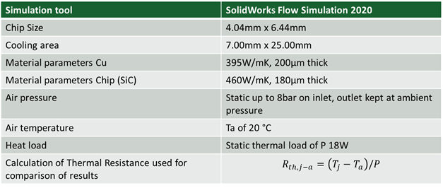
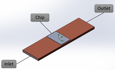
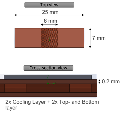
We performed simulations with SolidWorks Flow Simulation 2020 based on the conditions mentioned below, shown in fig. 1. For all thermal CFD simulations of the cooling structure, we applied the inlet and outlet configuration depicted in fig. 2. Unless stated otherwise, we kept the cooler area, as well as the chip position, constant for all simulations and comparisons. The cooler is comprised of four individually structured copper layers with a thickness of 200 µm each. The first layer acts as cover. The following two copper layers form the cooling channel. The last copper layer forms the backside cover, see fig. 3.
Fig 1: Boundary conditions for the test
Fig. 2: Configuration of an inlet, outlet and a chip on cooling structure
Fig. 3: Top and cross-section view of a cooling structure
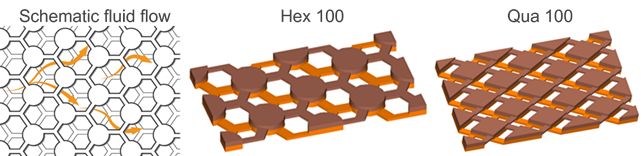
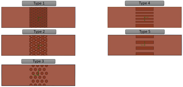
To run the simulations, we used three different cooling structures. Type 1 corresponds to Rogers’ Qua 50 structure and type 2 corresponds to a Qua 100 shown in fig. 4. It should be noted that Qua 50 uses 50% smaller geometries than Qua 100. Compared to these, we used a Hex 50 (type 3) and two standard lamellar coolers with five channels in the size 0.5mm x 0.4mm (type 4) and three channels in the size 1.00mm x 0.4mm (type 5), all shown in fig. 5.
Fig. 4: Left to right: Schematic fluid flow through a cooling structure; Detail of a Hex 100 and Qua 100 inner cooling structure
Fig. 5: Top view on cooling structures, five different types are shown
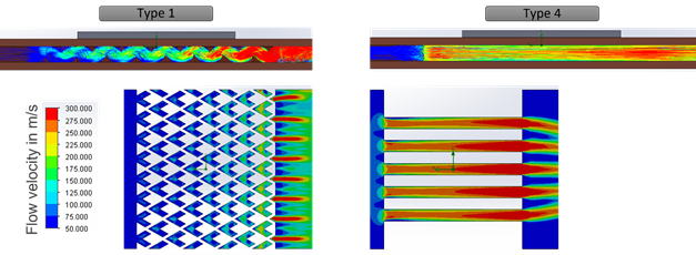
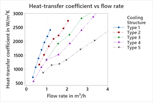
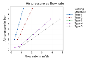
Fig. 6 shows the flow velocity distribution of type 1 and type 4. We can clearly seen that in the channels of type 4, laminar flow is dominate while the cooling structure of type 1 supports a turbulent flow. This, in combination with a larger effective cooling area of type 1, leads to a higher heat transfer coefficient at the same flow rate, depicted in fig. 7. Here, the cooling structure type 1 has the highest heat transfer coefficient at the same flow rate. The smaller cooling structure of type 1, 2 and 3 also leads to a faster increase of the pressure on the inlet compared to type 4 and 5, shown in fig. 8.
Fig. 6: Top view on cooling structures, five different types are shown
Fig. 7: Heat transfer coefficient vs. flow rate
Fig. 8: Air pressure vs. flow rate
Improved performance in comparison with competition comes from a higher specific surface area, as well as a maintained turbulent flow. For certain areas of application, air cooling can be superior to water cooling due to its simple availability, despite the worse thermal performance of air itself. Likewise, liquids are not often used in electronics due to the risk of leaks. Assuming, compressed air up to 90psi is relatively common and available at manufacturing locations, Rogers’ Type 1 micro-channel structure realizes about 50% lower operating costs versus cooler type 4 and 5. Calculating with 7.000 working hours per year times 0,02€ m³/h this accounts for 140€/year less per unit.
Our next steps are to confirm simulation results through tests carried out on our test bench and in customer applications. Another target is to also optimize cooling structures for air cooling use cases to improve performance and cost. For further information, please get in touch to discuss or have a look at our paper presented at Photonics West 2022.
[1] AMS Technologies, “Cold Plates”, https://www.amstechnologies-webshop.com (16 December 2021)
[2] Hughes, S., “Air-cooling Vs Water-cooling For Electrical Infrastructure & Industrial Equipment” processindustryinformer, 16 December 2016, https://www.Air-cooling Vs Water-cooling Infrastructure & Industrial Equipment (processindustryinformer.com (16 December 2021)
Do you have any question or require some information about our busbars? Please contact us, if you need assistance.
Published on Jan 24, 2022